A scheduler may seem too simple and too efficient to qualify as a multitasking operating system. You write all the code, there are no operating system commands to learn, and you can achieve full real-time performance. In one sense a scheduler just makes good use of a real-time clock. Yet the concept is so powerful it rates its own chapter [this post is from chapter13].
What is a scheduler?
Chapter 11 Hardware: Interrupts & Timers went into detail on the production of a regular interrupt—a real-time clock running tasks at specific times is a scheduler. It is an arrangement of software that calls task functions after a specific number of system ticks. Suppose you have a system tick every millisecond. You might have a keyscan task running every 40th tick and a stepper motor pulse task being called every 10th tick (100 steps/S). If the step rate changed, the scheduler might call the step function every 20 ticks (for a 50steps/S rate). All the activities key off counters initialized for a desired delay and then decremented every tick interval. When the counter for a specific task reaches zero, the count is reset, and the given task function is called.
Since scheduler tasks have to fit in between system ticks, you should write the code of any task to execute as quickly as possible and return. Never write while() or for(;;) loops in a task if exiting the loop depends on an outside event. Likewise, if there is a lot of processing to do, set a flag in the scheduler interrupt. Have the main function poll and detect that flag and then handle the processing in the background.
Example: Basic Traffic Light.
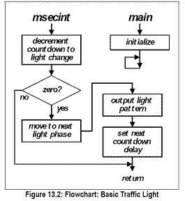
A traffic light program such as the one coded in Figure 13.1 and flowcharted in Figure 13.2 illustrates a scheduler quite well; lights should change at specific, regular times. A normal step in a light cycle consists of sending out a light pattern and leaving it on for a specified number of ticks (1mS intervals in this example, shortened since we don’t want to take several minutes to test the program while developing it)
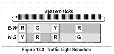
You may want to review “Structures” to follow the data storage—the light pattern and the hold time—kept in code space since they do not change. The structure named cycle holds the pattern of which lights are on or off as shown in Figure 13.3, as well as the number of millisecond ticks for which that part of the cycle should last. For demonstration I have made the cycle be 1, 3, 1, and 5S for a total of 10S; only in a fast-forward video could cars get through that!
#include<C8051F020.h>
#define uchar unsigned char
#define uint unsigned int
#define LEDS P1
uint countdown;
uchar index;
code struct{uint delay;uchar pattern;}cycle[]=
{{1000,0×12},{3000,0×41},//(0)=—R,–Y-; (1)=-G–,—R;
{1000,0×21},{5000,0×14}};//(2)=–Y-,—R;(3)=—R,-G-
void initialize(void){
WDTCN = 0x07;
WDTCN = 0xDE;//Disable WDT
WDTCN = 0xAD; XBR2 = x40;//enable crossbar
P1MDOUT = 0xFF;//P3 push-pull out
OSCICN = 0x04;//enable int oscillator
countdown=1;//start at once
index=3;//lead to first state
TMOD=0x10;//tmr1 16-bit
TH1=~(1000/256);
TL1=-(1000%256);
TR1=1;//enable timer 1
IE=0x88;//enable timer1 int
}
void msecint (void) interrupt 3 using 1{//this is the scheduler (only 1 task to manage)
uchar i;
TH1=~(1000/256); //restart the 1mS timer
TL1=-(1000%256);
if(–countdown==0){ //decrement & test for end
++index; //move to next phase of cycle
index%=4;
LEDS=cycle[index].pattern;
countdown=cycle[index].delay;
}}
void main(void){
initialize();
while(1){ ;//nothing to do in background
}}
Figure 13.1: Basic Traffic Light Program
Having the clock ticks managing the actual changing of the lights, the main (background) program can ignore time. (In the next example it will manage changes to the schedule if someone pushes a walk request button.)
During software development, for hardware I simulate the powerful, probably relay-driven lights of an actual traffic light with a few LEDs, and for rugged pedestrian walk buttons substitute inexpensive push buttons.
Development Hurdles The program found in Figure 13.1 is slow by a factor of about 5 or 6; I had forgotten that Silicon Labs’ internal oscillator defaults to about 2MHz (a 0x04 in the OSCICN register merely enables the internal oscillator) and the timer1 prescale defaults to a divide by 12, giving about 1/6 of the expected 1MHz rate into the timer. Since the original program assumed a 12MHz clock with a prescale of 12 giving a 1MHz rate into the timer and using a software divide of 1000 to get 1mS, there are three options to fix the rate:
- Change the 1000 divide in the software to about 167 so the 2MHz /12 gives 1mS.
- Program the oscillator frequency to about 14 or 7MHz (set OSCICN to 0x07 or 0x06). You will still need to adjust the software divide to about 1167 or 583.
- Change the prescale divide for the time (set CKCON to 0x10 so the timer1 input is SYSCLK instead of the default SYSCLK/12). You will then need a software divide of about 500 since the clock will come in directly at 2MHz.
Incidentally, I spent an hour wondering why the 8051-based program would not cycle through the states and kept re-initializing. Finally I realized I had forgotten the watchdog timer! It was timing out and restarting the program after the first cycle or so. The Silicon Labs processors have powerful extra features, but you must manage them carefully.


